|
|
|
|
|
|
|
|
|
|
|
|
|
|
|
|
|
|
|
|
|
|
|
|
|
|
|
|
|
|
|
|
|
|
[[Home | Experimental Aircraft | JT-5 Autogyro |3D Modeling] |
|
|
|
|
|
|
|
|
|
JT-5 Autogyro
Drawing Additions
|
 |
|
|
|
|
|
|
|
|
|
|
Questions and answers
Drawing Additions
Technical Photo Gallery
Pod and Canopy sections
Materials & Suppliers |
|
|
|
|
|
|
|
|
These
pages has been created to help builders in various countries to
complete their JT-5 autogyro project. I shall add new pictures and text
every nowand then to explain details and answer builder questions. |
|
|
|
|
|
Drawing additions:
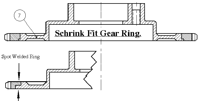
Sheet no.4. Some builders have requested an alternate
method for the rotor head main gear machining. One way is to use starter
gear ring from an outboard motor or other small engines. A 77Z starter
gear rings can be found in Rotax 503 and 505 engines, which can be used
in the JT-5 prerotator if the dimensions of the rotor head assembly is
altered slightly. Only the ring must be hardened to HB 240-280. You can
use schrink fit, spot welding or other methods to fit the gear ring. |
|
|
|
|
 |
|
|
Sheet no. 9
The following information was missing from the first 4 sets of
drawings. I added it to next ones. Please print and add the following
text and picture onto the sheet no.9. |
|
|
|
 |
|
|
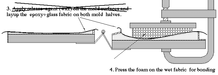
Correction:
I have mentioned twice (in poin1 and 3) that the mold surfaces should
be vaxed. Please remove the second text on Point 3 on sheet 9. |
|
|
|
 |
|
|
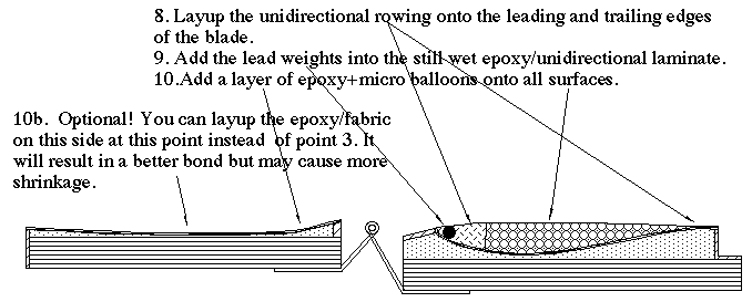
Optional addition!
You can layup the epoxy/fabric on the left side mold at point10 instead
of point 3. Actually I recommend this method since you dont need to
roughen the the layup surface. This note has been added to the drawings
starting 01.01.2000. |
|
|
|
|
|
 |
|
|
|
|
|
|
|
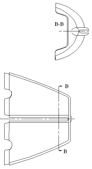
Sheet no.8 Replace the section C-C text on sheet 8 by B-B as shown below. |
|
|
|
|
|
|
|
|
|
|
 |
|


