[Home | Experimental Aircraft | Virtual Aircraft | Gyro Computation |
| Composite Propeller | Safety | Hobbies| Site Map
JT-11, JT-12, JT-13 and JT-14
Jukka Tervamäki 2009
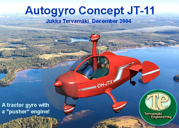
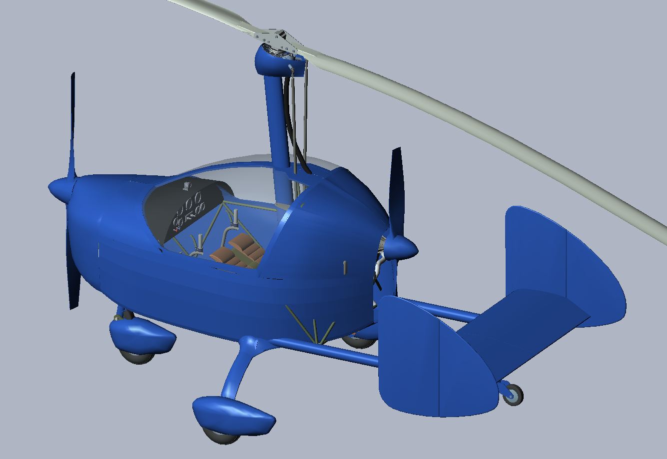
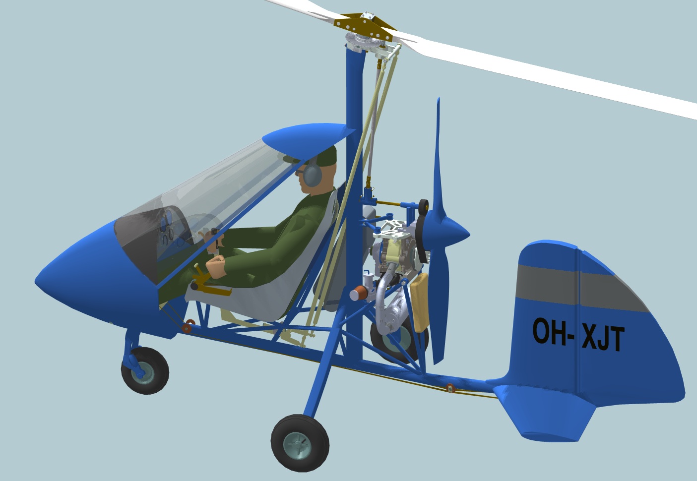
JT-11, a 2-seat tractor gyro with a pusher engine!
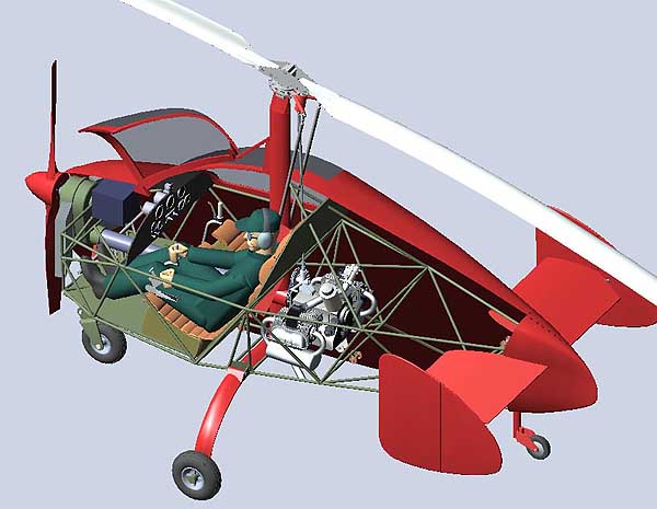
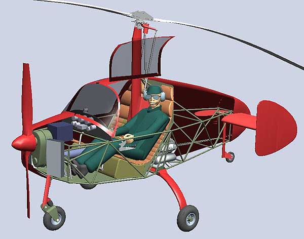
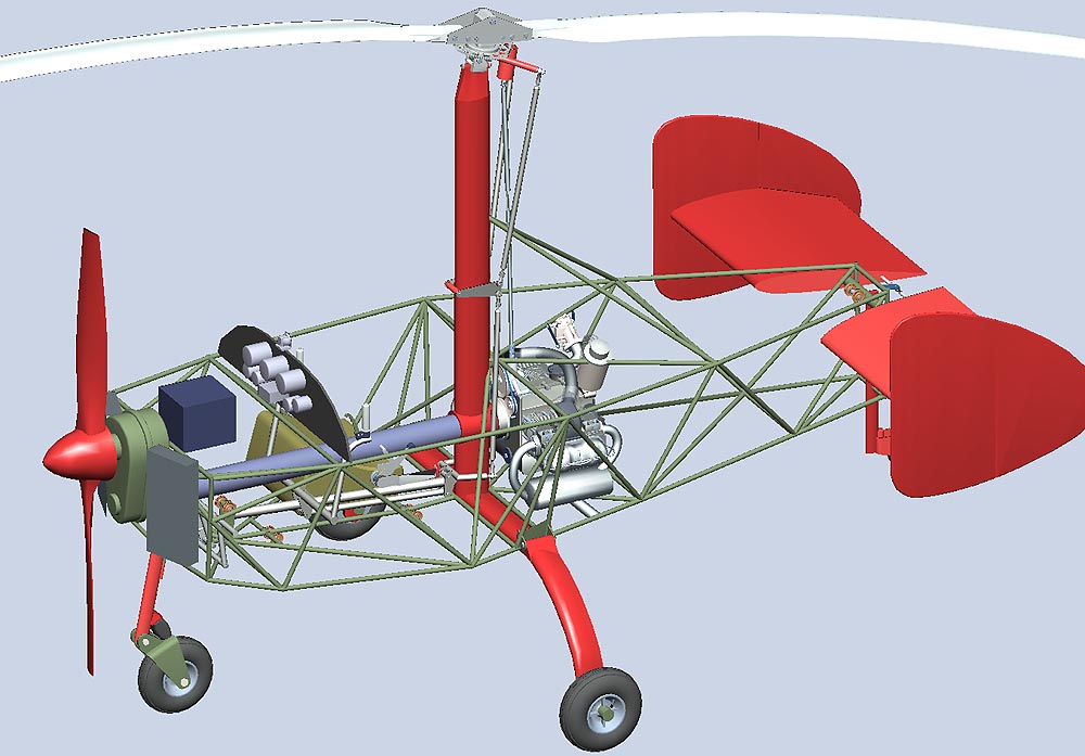
The JT-11 autogyro concept is a 3D modelling project with the purpose of evaluaiting a side by side tractor gyro design with no compromises in pilot visibility, propeller efficiency, gyro loading or the CG position.
Why a tractor? Pusher gyros have two main benefits, good helicopter like visibility from the cockpit and a fairly simple load carrying structure, with all main loads (engine, pilot, fuel tank and main landing gear) attached to the rotor mast. The biggest drawback of pusher gyros is the limited space (between keel tube and rotor) for an efficient propeller. In a tractor gyro one can use an airplane-like big diameter propeller offering a much improved efficiency.
Side-by-side seating is a much preferred seating arrangement by many pilots. However, in gyros, pushers or tractors, this arrangement creates a problem with the CG position when the gyro is flown with one very light pilot or with two heavy ones. In tandem gyros this problem is avoided. The pilot balances the engine weight and the passenger is seated right in the CG-position. The gyro can be flown with or without a passenger with minimal CG-shift.
With the JT-11 concept I wanted to achieve the following goals:
1) A tractor design with a big, efficient propeller
2) Side-by-side seating
3) Good forward visibility for both pilots. Rotor mast, prerotator and control rods should not be in the pilots view
4) A short prerotator shaft to the rotor
5) No (or minimal) longitudinal CG shift with one or two pilots on board
6) Fuel tanks should be right in the CG position, so that there is no CG shift when the fuel is consumed.
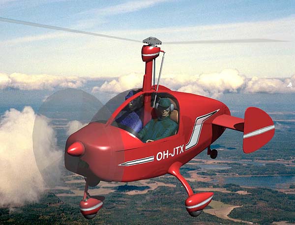
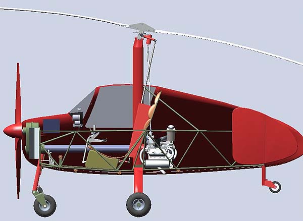
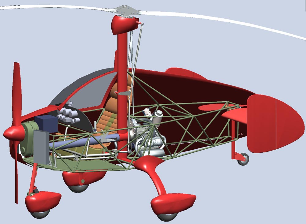
I achieved these goals by placing a part of the power plant (the engine) in the back and another part (propeller, reduction unit, cooling radiators and the battery) in the front of the aircraft. This arrangement balances the empty aircraft so that the longitudinal CG position is right where the pilots are sitting and by placing fuel tanks under the seats all the changing usefull load is in the CG.
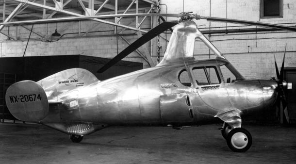
I am not the first one to figure out this arrangement. Although no such gyros exist today, Harold Pitcairn was the designer of the thirties who extensively used this arrangement in his last gyro designs. The Pitcairn PA-36 or AC-35 (?)
is shown below. One can easily recognize the cooling air intake behind
the pilot seats and the very small cowling on the nose which only
offers enough space for a reduction unit. The propeller shaft also is
higher than the engine revealing the power train principle. I have not
seen the Pa-36 in the museum nor any drawings of its power train.
The JT-11 utilises a 1.5 m long drive shaft from the engine to the reduction unit. It is a well known fact that long drive shafts create problems. Torsional vibrations are the most serious of them and can ruin the whole power train unless dampers are installed. A V-belt or a cogged belt drive reduces vibrations to some extent but often additional means are necessary.
Molt Taylor used Flexidyne couplings in his Aerocar, Imp and Mini Imp designs. The German Stemme S-10 motorglider has a power train which includes the following components:
1) V-belt drive
2) Flexible coupling
3) Carbon-Fibre drive shaft contained in a Kevlar tunnel
4) Splined sliding joint
5) Torsional Vibration Absorber
6) Centrifugal Clutch to avoid stop/start shock-loads
The JT-11 power train should be something similar. Of course, this adds weight and complexity. But this is the trade-off one has to accept to achieve the above goals.
3-view drawing in pdf-format is available for downloading. The drawing size is ISO/Din A0 for printing with the biggest plotters.
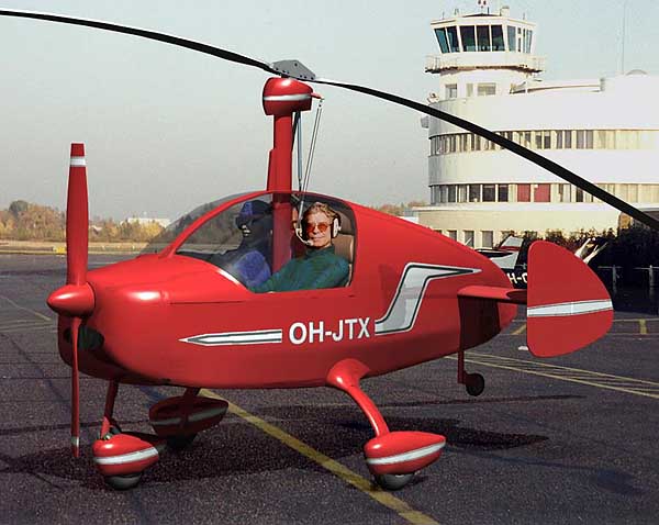
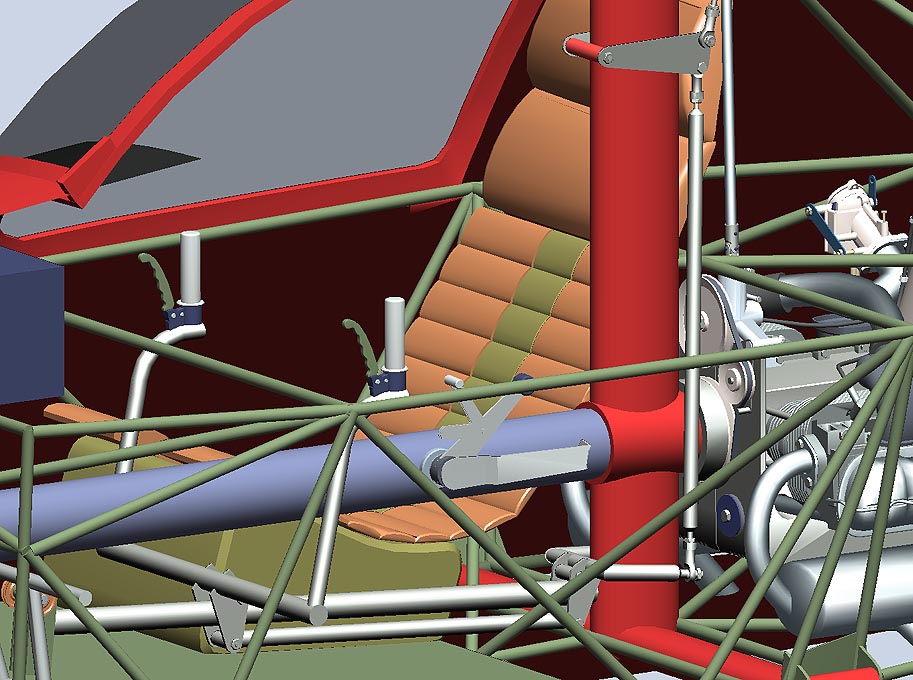
Click the pictures to view the bigger size! Pictures 7, 8 and 9 below show a revised control system giving more space for pilot shoulders.
 |  |  |
 |  |  |
 |  |  |
JT-12, a twin engine push-pull gyro.
This design offers similar CG advantages as the JT-11 concept with the addition of twin engine safety. Two HKS 700 engines could be installed and the gyro should be able to fly level with one engine only. Drawbacks: Complexity and cost.
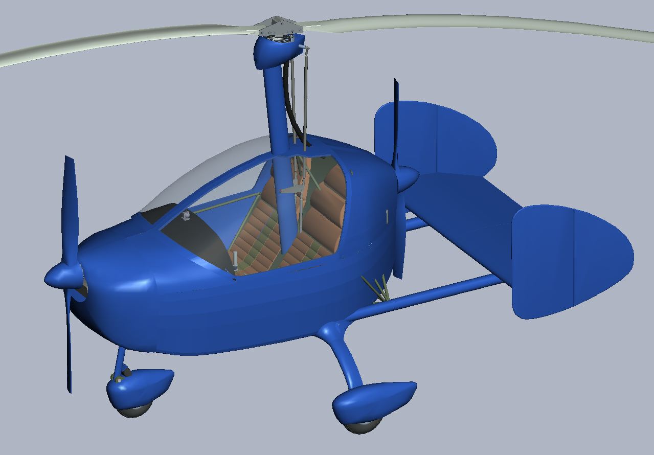 |  |  |
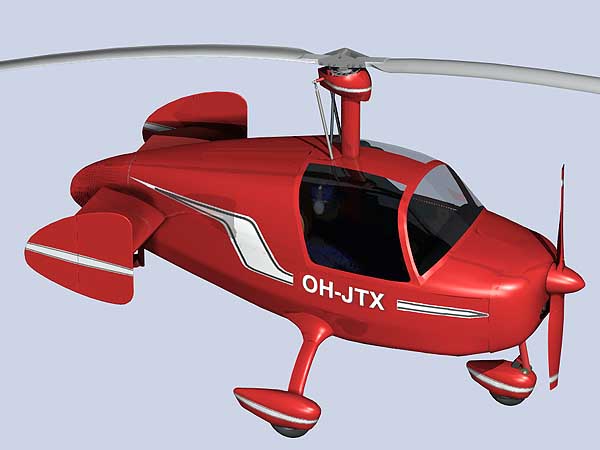
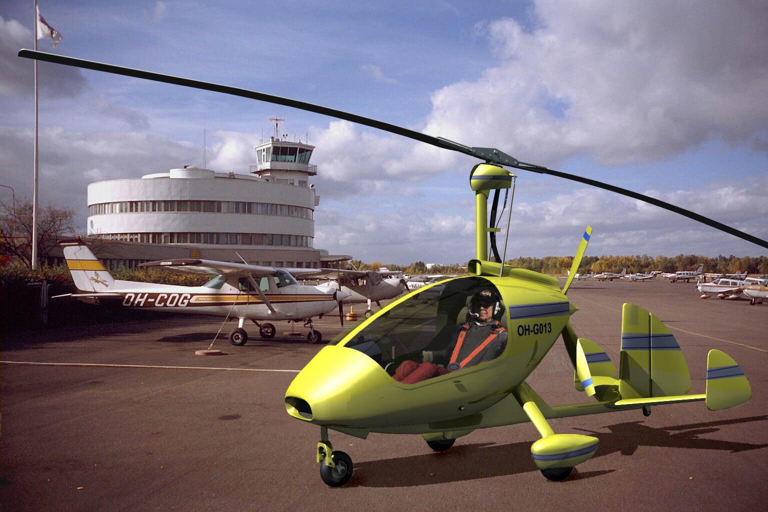
This variation was inspired by the availability the 115 hp Turbo Rotax engine. This engine is installed in many 2-seat gyros (like Magni M24, Xenon, etc) but unlike in the other gyros I wanted to try the possibility to install the cooling radiator on the nose of the aircraft. The cooling hoses are inside the aerodynamic casing under the belly. The air flow to the tail planes would be smooth with minimum turbulence and a simple valve in the wall between radiator space and cockpit would provide cabin heating which is a necessity up here in the north.
I also wanted to see if the readily available aluminum rotor blades could be installed in the JT-type rotor head. The answer appears to be yes.
 |  |  |
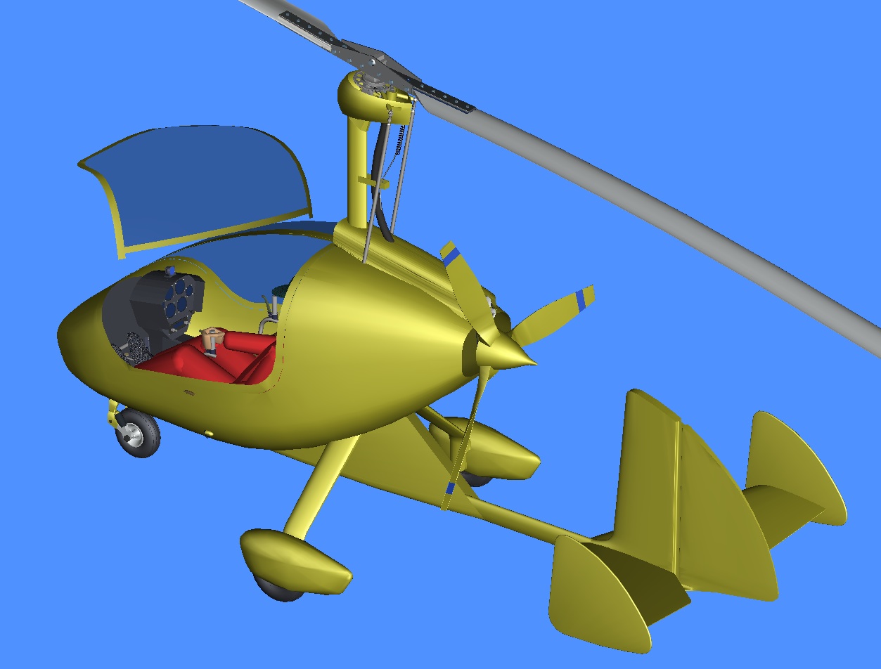
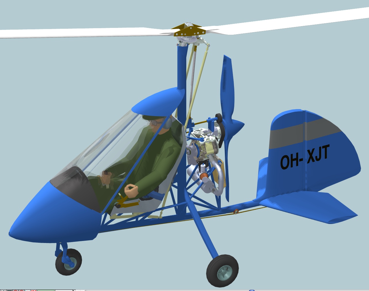
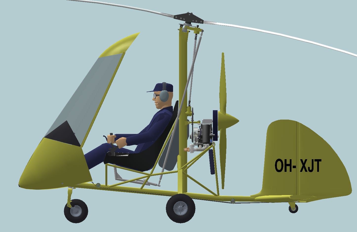
This is my idea of a minimum gyro. Yes, Bensen made it already 60 years ago (B-7m) powered by a 40 hp Nelson engine. Today an even lighter engine is available, the Aixro rotary engine. It already has flown over the Mount Everest in a powered paraglider. So the Aixro engine should be a good choice for a very light autogyro. More info on the Woelfle web site.
In my design concept the canopy tilts forward for easy pilot access to the seat.
 |  |  |
If you feel these designs are interesting, please send me your comments 
Comments:
1) JT-11 looks very interesting! And well conceived. You will not find a
PA-36 museum reference as the only flying model was cut up for scrap in
1942-3. Harold Pitcairn had the cutting up filmed. It marked the end of
his Autogiro development/involvement. There was a second aluminum body
constructed by Luscombe, but it too was cut up and the aluminum donated
to the war effort.
Bruce Charnov, Hofstra University, New York
2)
I love the JT-11 concept. It sure would be great if someone would put
this into production. It is a beautiful design. The configuration is
very compact and should have a very good power/weight ratio. This also
allows complete aerodynamic enclosure of the engine - good
performance?! Would the weight of the drive system offset the
configuration weight savings?
Greg Gremminger, USA.
3) I saw the design concept for your JT-11 Autogyro on your website. It is brilliant!
Clifford Rock, USA
4)
Gyrokonseptisi näyttää näin keskinkertaiselle heko-experimental
miehelle hienolta (tuttuun ammatimaiseen tyyliisi). Olisi kyllä hieno
saada joku rakentamaan sellainen. Onko kukaan ollut niin pitkälle
kiinnostunut (vielä)?
Pena
5)
Kylläpä olisi hieno projekti!!!! Sellainen pitäs
ehdottomasti saada tänne Suomeen. Meitä ainakin himottaisi
tollainen kone.
Make
6)
Nice design.. As soon as I finish my ultra light tractor gyro, I plan
on attacking just this sort of machine. The drive shaft issue has been
proven to work if done properly. Look forward to seeing this design
taken to the next level !!
Timothy Blackwell, Mentone, IN.
7) A beautiful concept! Tom Hughes Olympia, Wa.
8)
I couldn't believe my eyes! I have sketched out on paper something to
build just like this! Only main difference... I had the re-drive in the
back by the engine... I think I like you idea better (Lower drive
shaft! Also, it could spin slower...). Maybe we'll see this thing come
to life...
david
9) Well done once again, this is
exactly the configuration the world needs. I hope you will be able to
provide at least "advisory" drawings
so others may fill in the "missing bits", share information and get the JT - 11 airborne.
Yours in great esteem Jim Sherlock
10)
The concept seems excellent. I think this is an autogyro that would be
much desired by the rotor community, as a plans built, or as a kit. I
hope you continue to develop the design, and look forward to seeing
plans offered.
Lawrence A. Sciortino, USA
11) A
brilliant design, sometimes a little blast-from-the-past is just the
key. I too wonder if the re-drive (all or part) should not be in back
by the engine. Thank you, I will be following this design development!
Douglas White
12)
Let's say...your brain is a volcano! Thanks for brainstorming for
us all... My question is: how may I get plans to build the JT9 and/or
the JT11 rotorcraft? As I'm a quite well proven aircraft
home-builder, it could be sufficient also a not well finished set of
drawings. May I get plans of such beautiful birds?
Best regards Pierre Marcucci
13)
I was playing with the my idea of a push-pull gyro, when I remembered
your Virtual Gyro exercise: so I started messing with Paint to adopt
your JT-9, marvel to my imagination...
What an incredible cruise machine would it be ! I'd love to build one. Again, congratulations, Vincenzo Praturlon
14)
Have you ever tought about an ultralightversion of your JT-9
concept? A taildragger tractor built like the gyro bee or the
affordaplane, based on a single square tube?! And engines like the
Citroen Visa or Honda, Briggs and Stratton engines could be used, they
do not cost the world, and the airframe could be built for some €uros,
without ruining a houshold and scaring away the wife ! ;-) Would
you have an idea for such a JT-...?
My very best rgds from France. Erkki Müller
[Home | Experimental Aircraft | Virtual Aircraft | Gyro Computation |
| Composite Propeller | Safety | Hobbies| Site Map