|
|
||||||||||||
|
||||||||||||
| These
pages have been created to help builders in various countries to
complete their JT-5 autogyro project. I shall add new pictures and text
every now and then to explain details and answer builder questions. So,
the pages are a kind of a FAQ pages.
Click the pictures to see the bigger size! |
||||||||||||
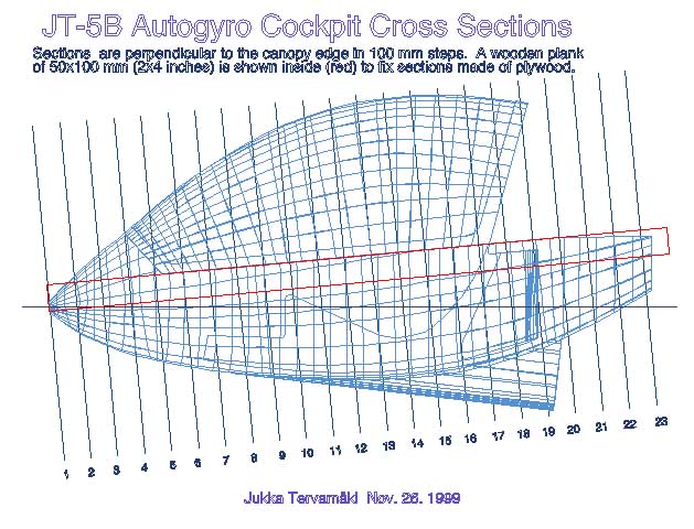
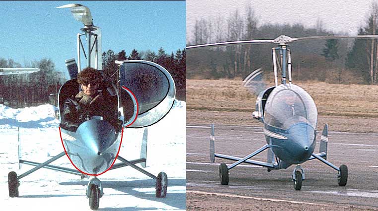
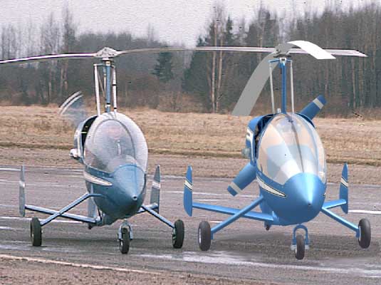
| New fuselage pod cross sections to build the plug for the mold. My 3D model may not be very accurate, it was not modeled to be a CAD info source but for visualization purposes in the first place. Nevertheless, it may be of some help to build the pod plug. Therefore, I have derived pod cross sections from the model in 100 mm steps. The sections are attached on this page as for pdf files (A4 and A1 size), two for the side view and two for the actual sections which are dimensioned. The pod is now sectioned perpendicular to the cockpit edge and I placed a wooden plank of 50x100 mm(2x4 in) size inside (red in the picture below) where the sections could be fixed if made of plywood. The plank is also a dimensioning reference. I also improved the canopy shape in the virtual model and the comparison can be seen on the picture below right. The real machine and model are sitting on the runway with the rotors tangled! The model canopy is now closer to a free blown shape and the new sections are in the pdf file.
NOTICE! Section 14 was erroneously same as No13. This has been corrected Dec.3.1999 on both the A1 and A4 size files. However, my Acrobat distiller made some strange artifacts on the A4 size file, page one. It is readable though. Download the side view pdf file, size A1! Download the side view pdf file, size A4! Download the section pdf file, Size A1! Download the section pdf file, four A4 sheets!
|
||||||||||||
| The original method of making the canopy and pod for the JT-5 were as follows:
Canopy: The Canopy was free blown by a roof window
manufacturer. Actually I experimented to get the proper blowing frame
shape by blowing 1 mm thick runbber sheet in 1/10 scale using compressed
air. Once I was satisfied with the shape I built a full scale frame of
wood and plywood and carried it to the manufacturer. A preheated
plexiglass sheet was taken from an owen, clamped on a blowing fixture by
compressed air cylinders and them blown up and up. The second try gave
good results. I did not have any sections but I did have the height and a
side silhuette female shape made of plywood. When blowing reached this
shape we stopped. Blowing requires a great deal of expertise, but I was
lucky, the men knew what to do. They cooled, sometimes heated an area of
plexiglass sheet to get a smooth contour. Actually I made the canopy
first and shaped the pod according to canopy shape on the nose area.
That is why they fitted so well together.
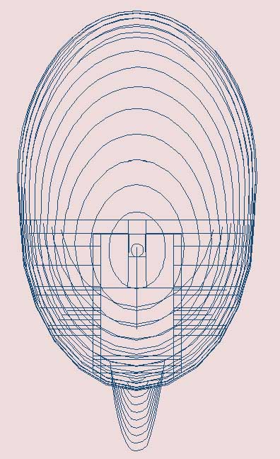
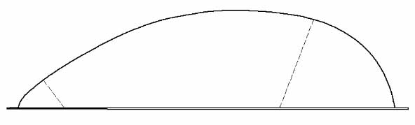
Shown below is the general idea of the canopy shape when blown from an acrylic sheet. The dotted lines show where to cut.
|
||||||||||||
|
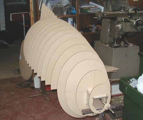
Cockpit pod: I built my JT-5 mold using a scrapped
glider fuselage as a template for the plug. After the sawing, cutting,
glass layup and filling no original shape was left. To make the plug
rigid a wooden structure was added inside. The seat mold was made using
the glider seat parts as a template. The fuel tank was laminated using
temporary sheet metal plates fixed on place by modeling clay (play
dough).
Philip Mac Cabe (maccabep@ie.ibm.com) of Ireland.is the first builder to show fuselage pod plug taking shape.
|
||||||||||||
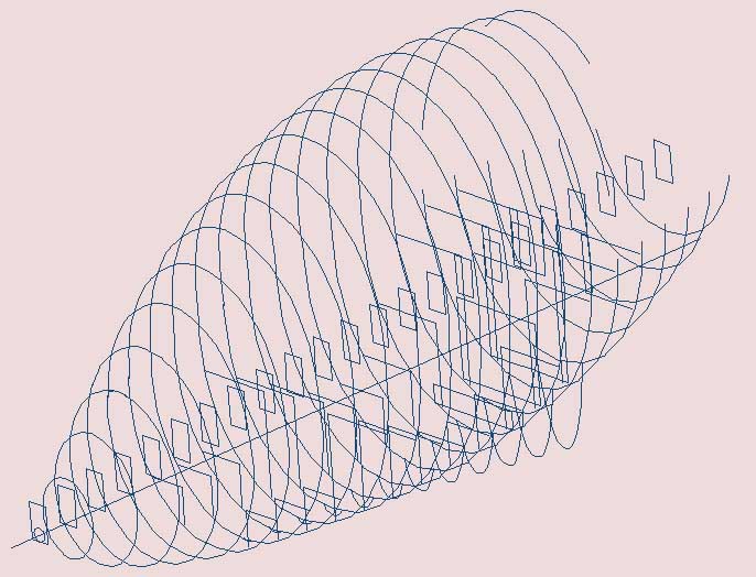
| JT-5 3D model. To view some construction details, I have modeled the JT-5 autogyro using formZ RenderZone modeling
software. The model even includes the Limbach engine and a pilot (me!)
and shows details down to the nut and bolt level. Make a visit to my 3D page.
|
||||||||||||
|
|
||||||||||||

